Normals, Matrices and Euler Angles
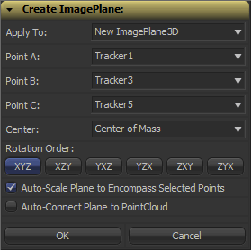
 Fusion can import point clouds from a 3D camera track, but there’s no easy way to align an image plane to three points in space. If you want to place walls or floors for camera projection setups, this makes for a tedious task of tweaking angles and offsets. So, I’ve been dusting off my math skills, especially transformation matrices, to write a script that allows you to place an ImagePlane3D or Shape3D with just a few clicks.
It’s a tool script that goes into your Scripts:Tool folder. You need to select a PointCloud3D before running it. Unfortunately, there’s no way for the script to know which points of the point cloud you have already selected 🙁 You need to hover your mouse over the point cloud vertices after you have launched the script to read their names and select the desired points from a list. The script will, however, remember your choices so you can play around with various trackers quickly and you can choose to apply the transformation to existing planes instead of creating new ones. Here’s a video of the process:
Here’s a script to freeze cameras for projection setups easily.
In case you’re curious: these are the steps that are necessary to solve this problem. Maybe it’s useful to somebody solving the same problem.
- A plane is defined by three points, which we have, but Fusion needs a center offset and three Euler angles move an object in 3D space.
- The center can be chosen almost arbitrarily: any point that lies on the plane is fine. For my script, the user is able to choose between one of the three vertices or their average (which is the triangle’s center of mass). The rotation angles can be deducted from the plane’s normal vector.
- To get the normal vector, build two vectors between the plane’s three vertices and calculate the cross product. This will result in a vector that is perpendicular to the two vectors and thus perpendicular to the whole plane.
- This vector alone won’t give you the required rotation angles just yet. You need a rotation matrix first. According to this very helpful answer on stackoverflow, a rotation matrix is created by three linearly independent vectors. These are basically the three perpendicular axis vectors of a coordinate system that has been rotated. One of them is the normal vector (which is used as the rotated Z axis). The second one could be one of the vectors we used to calculate the normal vector. However, there’s an algorithm that can produce a better second vector, one that is aligned to the world’s XYZ axes as closely as possible. This is useful since the plane we’re creating is a 3D object with limited extends instead of an infinitely large plane.
- The third vector we need can again be calculated using the cross product between the normal vector and the result of the previous step.
- To decompose a rotation matrix into Euler angles, there’s a confusing amount of solutions on the web since there are several conventions: row vectors vs. column vectors, which axis is up and most importantly, what’s the desired rotation order (for example XYZ or ZXY?). Fusion uses row vectors and supports all 6 possible rotation orders, so we’ll go with that. The source code can be found in Matrix4.h of Fusion’s SDK. Moreover, this paper (“Computing Euler angles from a rotation matrix”) explains the process quite well.
thx u to!